
Accurate technical engineering drawings are the foundation of successful custom glass procurement for vehicle manufacturers, architectural system suppliers, and commercial appliance producers. Incomplete or ambiguous glass drawings result in production delays, mismatched CNC tooling, and costly dimensional disputes. This guide details standard engineering drawing elements, geometric dimensioning and tolerancing conventions, and RFQ package requirements.
Essential Engineering Drawing Elements for Custom Processed Glass
A production-ready glass engineering drawing must convey all geometric, thermal, and decorative requirements without ambiguity. Unlike metal or plastic fabrication, glass cannot be bent, reamed, or modified after thermal tempering. Every hole, cut-out, edge grind, and screen-printed graphic must be finalized before the raw float pane enters the processing line.
Key drawing title block requirements include formal revision control numbers, date stamps, target glass substrate type, nominal thickness with allowable thickness tolerances, and clear surface side definitions (Side 1 exterior through Side 2 interior). For tailored component sourcing across both sectors, consult our automotive glass and appliance glass hubs.
Datum Alignment Systems and 3D Curvature Coordinate Tolerancing
For curved vehicle glass or complex contoured appliance panels, establishing a clear Cartesian coordinate datum system (X, Y, Z axes) is essential. Drawings must identify three primary datum points on the glass surface to fix the component orientation inside inspection fixtures.
Curvature should be defined using 3D surface files (such as STEP or IGES format) supplemented by 2D sectional cross-sections showing local sagitta heights. Surface profile tolerances are typically specified as bilateral tolerances (e.g. ±1.0mm) relative to the nominal CAD surface model.

Geometric Dimensioning and Tolerancing Standards for Glass Components
Applying standard mechanical Geometric Dimensioning and Tolerancing (GD&T) principles according to international mechanical drafting standards ensures clear interpretation between customer engineering teams and factory CNC programmers. A primary, secondary, and tertiary datum reference frame (Datum A, B, C) establishes repeatable inspection alignment.
For mounting holes, drawings should specify true position tolerances (e.g. true position within 1.0mm diameter relative to Datums A, B, and C) rather than simple linear coordinate ranges. This accommodates slight machine positioning variations while ensuring fastener pins seat perfectly during assembly.
Specifying Edge Finishes, Notches, and Precision Internal Cut-Outs
Drawings must explicitly call out the required edge finishing profile using standardized industry terminology. Specifying simply "ground edges" is insufficient; drawings must distinguish between arrised edges, pencil/C-edges, and flat polished edges with specified chamfer widths.
For internal cut-outs, minimum internal corner radii must be dimensioned. Internal sharp ninety-degree corners cannot be machined with rotating diamond tools and create extreme stress risers; all internal corners must specify a radius of at least the glass thickness, with 6mm to 8mm being standard for commercial reliability.
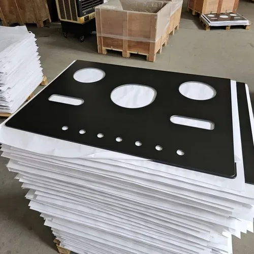
Ceramic Frit Ink Specifications, Optical Density, and Electrical Busbars
When glass components require decorative or functional ceramic printing, drawing documentation must include dedicated artwork layers and ink specifications.
| Required Engineering Callout | Common Procurement Error | |
|---|---|---|
| Ceramic Enamel Color | Standardized color code (RAL / Pantone) and opacity | Vague description such as "glossy black" |
| Printed Surface Designation | Specify Surface 1, Surface 2, or both | Omitting print side, leading to mirrored artwork |
| Hole-to-Edge Distance | Minimum 2x glass thickness from edge to hole rim | Placing holes too close to edge, causing furnace cracks |
| Conductive Silver Grid | Grid line width, spacing, and target resistance (ohms) | Omitting electrical parameters for demisters |
| Corner Radii | Explicit corner radius (e.g. R5.0mm ±0.5mm) | Assuming sharp 90° corners are acceptable |
First Article Inspection and Production Part Approval Process
Large-scale automotive and appliance manufacturing contracts require formal First Article Inspection (FAI) or Production Part Approval Process (PPAP) documentation prior to commercial production release. The FAI report cross-references every numbered balloon callout on the customer engineering drawing against actual physical CMM measurements taken from initial tooling parts.
Key submittals include material chemical analysis certificates, surface compression stress measurements, fragmentation test break patterns, and salt spray corrosion test reports for ceramic frit enamels and demister busbar soldering.
Bilateral vs Unilateral Tolerances and CMM Coordinate Verification
When preparing manufacturing drawings, design engineers must choose between bilateral and unilateral tolerance schemes. Bilateral tolerances allow equal deviation above and below nominal dimensions (for example, 800mm ±1.0mm). In contrast, unilateral tolerances constrain variation to a single direction (such as 800mm +0.0mm / -1.5mm), which is commonly specified for glass panels fitted into rigid extruded aluminum channels where oversize glass cannot be assembled.
Quality verification for complex curved glass is executed on multi-axis coordinate measuring machines (CMM) or non-contact optical 3D blue-light scanners. The measured surface cloud is digitally aligned against the native CAD model using best-fit alignment algorithms to generate color-coded deviation heatmaps for factory sign-off.
Defining Sample Approval Stages: Initial Prototypes to Golden Samples
Large-scale OEM component procurement should establish a formal multi-stage sample sign-off procedure before authorizing full production runs. Initial soft-tooling prototypes verify basic dimensional fit and assembly clearance within the customer vehicle or appliance chassis.
Following prototype approval, pre-production "Golden Samples" produced on mass-production tooling are inspected against full checking fixtures. Signed golden samples serve as the binding physical benchmark for subsequent container deliveries.
Comprehensive RFQ Package Checklist for Fast Supplier Quotation
Supplying a complete, professionally prepared RFQ package allows suppliers to return fast, competitive, and technically accurate quotations. Submit your complete engineering RFQ package directly through our RFQ portal.
- Clean 2D vector PDF drawings with all dimensions, tolerances, and notes.
- Native 3D CAD models (STEP/IGES) for curved panels or complex CNC cut-outs.
- Detailed ceramic frit artwork files (1:1 vector DXF or high-resolution PDF).
- Substrate specification: glass type, color, thickness, and thermal treatment.
- Inspection standard requirements and checking fixture gauge specifications.
- Projected annual volume, batch batching schedule, and packaging requirements.
Frequently asked questions
What is the standard tolerance for hole diameter in architectural and OEM glass?
Standard hole diameter tolerances for CNC-drilled glass range from ±0.5mm for holes under 25mm diameter to ±1.0mm for larger cut-outs, depending on glass thickness and fabrication machinery.
Why must hole locations be dimensioned from a single datum corner?
Dimensioning hole locations progressively from hole-to-hole compounds manufacturing tolerances. Establishing a single reference datum corner ensures that position tolerances remain strictly independent across the panel.
Can CAD files replace 2D dimensioned engineering drawings for an RFQ?
While 3D CAD files are vital for CNC toolpath programming, 2D drawings remain legally binding documents that specify critical non-geometric data such as edge finishes, surface designations, optical standards, and legal revision approvals.
What file format is best for submitting ceramic screen-printing artwork?
Vector-based formats such as 1:1 scale DXF, DWG, or vector PDF are required for photolithographic screen production, ensuring razor-sharp edges and accurate dot-matrix gradients.
What is the difference between a bilateral and unilateral tolerance in glass drawings?
A bilateral tolerance allows variation in both positive and negative directions from the nominal dimension (e.g. 500mm ±1.0mm). A unilateral tolerance restricts variation to one direction only (e.g. 500mm +0.0mm / -1.5mm), which is commonly used to ensure glass panels fit inside fixed metal channels.
Sources
- ISO 128-1: Technical product documentation — General principles of presentation — International Organization for Standardization
- ASME Y14.5: Dimensioning and Tolerancing (GD&T Principles) — American Society of Mechanical Engineers